LAB 02 CprE 305
The purpose of this lab assignment is to help you become more familiar with
verilog as well as the Max Plus II simulation tools.
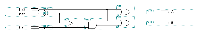
- The following is a diagram for a 4-2 priority encoder, with line ina0 removed (since it has no effect on the output).
Construct the truth table for the schematic.
- Use verilog to construct the encoder.
- Simulate your circuit and verify the results
with your truth table. Your simulation results should be very easy to read,
similar to the style of your truth table.
- Show your TA the truth table, your verilog
code, and your verified simulation results.