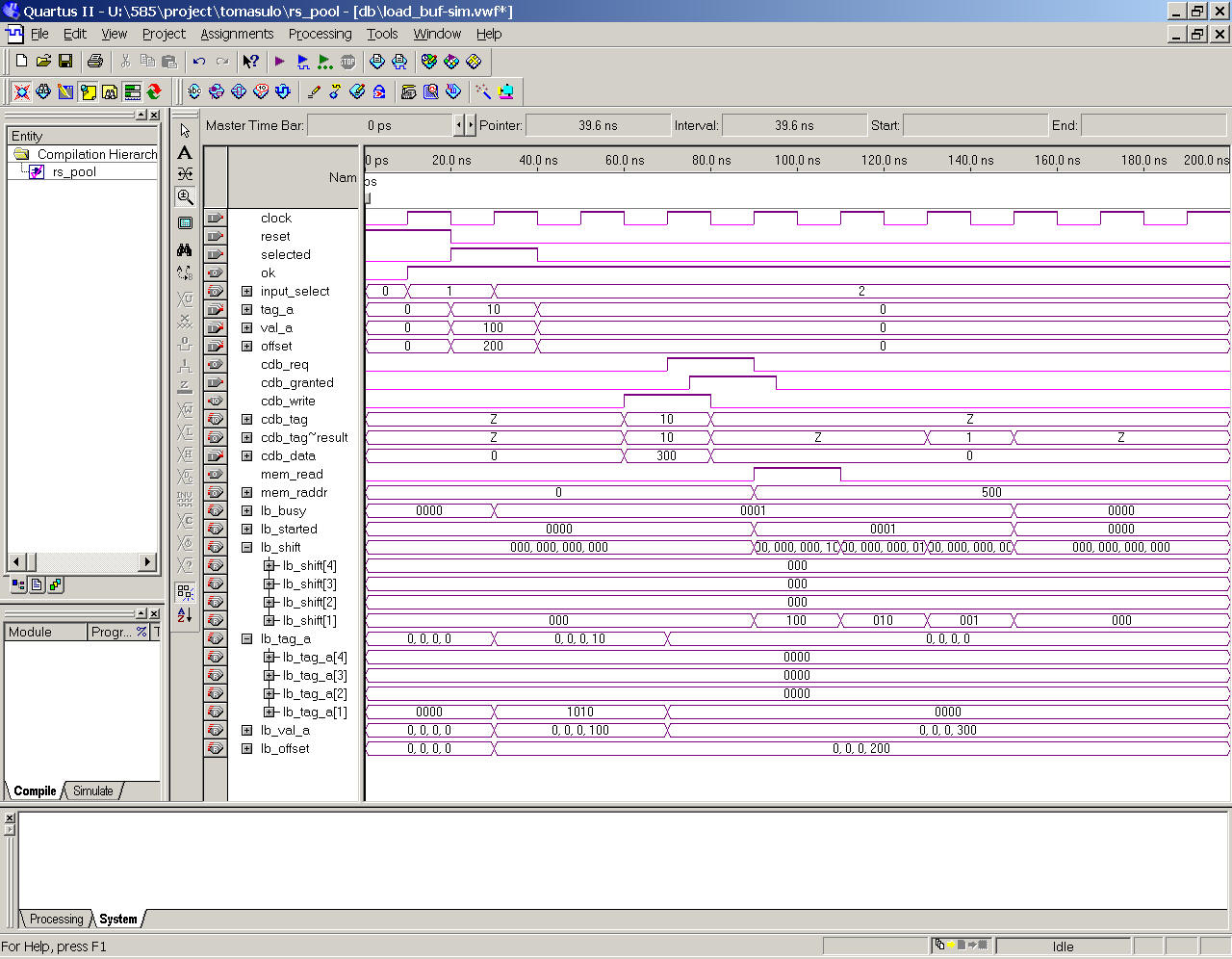
Load buffer testing sample:
Cycle 1: The load buffer is reset. Note that ok is raised, indicating the load buffer is ready to accept new instruction. The tag for the new instruction, if the load buffer is selected, is given by input_select (the first select is 1).
Cycle 2: The load buffer is selected to receive a renamed load instruction with tag_a = 10, val_a = 100, and offset = 200. Note that the values are recorded in lb_tag_a[1], lb_val_a[1], and lb_offset[1], respectively. Lb_busy[1] is set to indicate the load buffer entry is in use. Since the tag value is 10, the instruction will wait in the load buffer for its parent instruction to finish.
Cycle 3: Nothing is happening. The instruction is being kept in the load buffer.
Cycle 4: The parent instruction is broadcasting its tag and data. Lb_tag_a[1] is reset to zero and lb_val_a[1] accepts the new data 300 (it is the base portion of the load memory address). At the same cycle, the load buffer raises cdb_req (sent to cdb_arbiter) for CDB arbitration. The request is granted at the same cycle (cdb_granted=1).
Cycle 5: The load buffer raises mem_read signal and send mem_raddr (200+300=500) to data memory. Then it sets a shift counter (lb_shift[1]) to track the completion of memory read.
Cycle 7: The memory read completes at this cycle. The load buffer is to release entry 1 for further use.
Cycle 8: Now entry 1 has been release (lb_busy[1]=0).
Here cycle n refers to the nth raising clock edge. In a full simulation, the hardware processes would happen between the (n-1)th raising edge and the nth raising edge.
The CDB arbitration is a tricky point: the request is raised when an instruction is to be sent to a functional or memory unit. The instruction uses the CDB k cycles later, where k is the latency of the functional/memory unit. Read cdb_arbiter.v to understand this procedure.
You can use this testing sample as a template in designing your testing sample for reservation station.